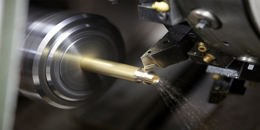
We live in a technical world today where the uses of custom CNC parts can never be over emphasized. These CNC parts are very important aspect of CNC Machining. Almost every high tech manufacturing company in our economy today utilizes CNC Machining.
What makes this concept so special? CNC Machining makes use of automated processes in the production of machined parts. They are not only easy to navigate, they also save cost in production.
This method also allows you to attain a level of accuracy and complexity. Something you might not be able to do with other machining processes.
How to Design a CNC Machining Part: Things You Should Know
As automated as this process may seem, you wouldn’t be able to get your desired results if you don’t pre-plan. The industry does not set up a common standard and that is why this process has remained difficult.
Machining methods and operations are continually evolving. This has made the process even more complex.
However, some general rules have been created to enable operators get round the process. Applying these rules while designing a CNC Machining part will enable you decide on how to achieve a ffeasible and high quality design.
Holes
Usually, operators makes use of drill bits when machining parts. If you want to decide how wide or narrow you will make a hole, use standard drill bits of dimensions measured in imperial units.
Technically, it is possible to achieve a diameter above
One millimeter. Operators normally use boring tools and reamers if they need to create a highly tolerant hole.
Threads
Usually, the size of a thread is M6. It could be higher if you are designing a CNC machined part. The minimum possible measurement is M2.
Most times, Engineers make use of CNC threading tools in reducing the size of threads to M6. This reduction in size also lowers the risk of tap disrupting.
Internal Edges
For internal edges, the approved radius for the corner is one third of the cavity depth or more. Using this recommended figure will entail using a diameter tool.
This rule is in compliance with the approved cavity depth guidelines. If you use a corner radii slightly higher than what was recommended, it will be possible for you to cut through a round part of degree other than 90.
This is particularly important because it improves the quality of the CNC parts
Cavities
The approved depth of a cavity is usually times four that of its width. It is made this way because the cutting length of end mills is restricted.
This restriction is usually 3-4 times of the diameter. If a depth-to-width ratio is low, it could lead to increased vibration, chip evacuation, and deflection.
To solve this problem, all you need is a variable cavity depth. A variable cavity depth helps you create more depth for your desired design.
Other things you should consider are the thickness of the wall, and other small characteristics.
Conclusion
Although CNC machining is automated, designing its parts is not as easy as it seems. Therefore it is important that you follow the laid out rules so your project wouldn’t end in a disaster.

